A Portable Rocket Rack
Contributed by BIT_EIMER
HTML conversion by Craig McGraw
Introduction:
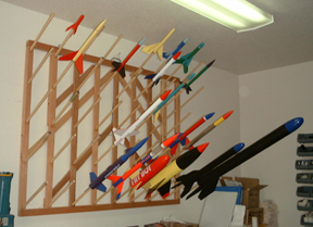
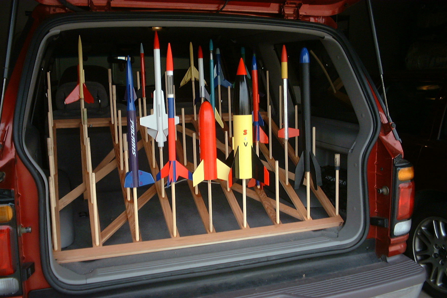
In early February 2003, I posted (on alt.binaries.models.rocket) some photos of a “rocket rack” I had just completed.
This rack displays/stores up to 45 rockets (13mm 'T' through 24mm 'E' engines), hangs out of the way on a wall,
allows easy transportation to a launch site, can be easily and comfortably carried with one hand, and sets up readily
at the launch site.
While the original implementation was done on-the-fly with no formal plans, in response to a number of requests, I
created the following plans “after the fact”. I have tried to make them accurate and comprehensive, but have not
“test flown” them on anyone to see where they might be in error or otherwise lacking. So keep in mind - you get what
you pay for! ;^)
Nevertheless, I hope you find them clear and effective. Thanks to Scott Hansen for his unsolicited offer to host
these plans. If you build a rack based off of these plans, feedback in the form of comments, criticisms, kudos, and
photos would be appreciated.bit_eimer@cox.net
Design Goal and Theory of Operation:
I wanted to get all the family’s rockets organized in one place and free up my tool pegboard where they had been
hanging. I also wanted a means to transport the rockets to a launch site and keep them organized during the launch.
My solution:
A front frame with dowels angled up to hold the rockets on display combined with a back frame that would hinge out to
create a stable stand at the launch field. The ˝” dowels accommodate a 13mm rocket (T engine) directly, while
18mm (A-C) and 24mm (C11, D, E) rockets use spent engine casings as adapters. Magnetic catches hold the back frame
to the front during transport. In addition, a couple of foldout legs support the rack while in route in the car.
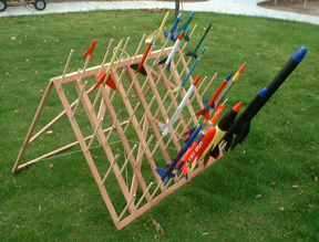
Here are some photos of the finished rack in various positions:

Parts List:
- 11 -- 1Ľ” x ˝” x 33Ľ” redwood *
- 4 -- 1Ľ” x ˝” x 47˝” redwood *
- 2 -- 1Ľ” x ˝” x 26” redwood *
- 2 -- 1Ľ” x ˝” x 34” redwood *
- 30” -- Ľ” braided nylon cord
- 4 -- ľ” screws with washers
- 4 -- 2” x 1Ľ” hinges w/screws
- 10’ -- 1/16” braided nylon cord
- 12” -- 1/8” bungee cord
- 5 -- small screw eyes
- 2 -- Ľ” lag screws
- 2 -- 1˝”-shank eye bolts with 4 washers and 2 nuts (large enough to fit over the Ľ” lag screw head)
- 12 -- 2Ľ” flathead screws
- 45 -- 11” x ˝” hardware dowel
- 2 -- magnetic cabinet-door catches
- -- felt padding strips
Optional Parts for “transport” legs:
- 2 -- 1Ľ” x ˝” x 15ľ” redwood *
- 2 -- 1Ľ” x ˝” x 17” redwood *
- 4 -- 1” x 1” hinges w/screws
- 2 -- magnetic cabinet-door catches
- 2 -- 2Ľ” flathead screws
Some (but not all) of the tools and supplies you may need:
- ˝” Forstner drill bit
- drill press or hand drill angle brace
- bar clamps
- epoxy
- wood glue
- grinder
- wood hardener
- wood glue
* I made the 1Ľ” x ˝” x XX” redwood from 5” x ˝” x 60” tongue-in-groove paneling from Home Depot.
BUILDING THE RACK:
 STEP 1 - Drill the dowel holes
Drill ˝” holes in the 9 vertical boards,
with a vertical spacing of approximately 6”. Angle should be approximately 30 degrees up from perpendicular.
The holes should be as deep as possible without punching through the backside.
 STEP 2 - Build the front frame
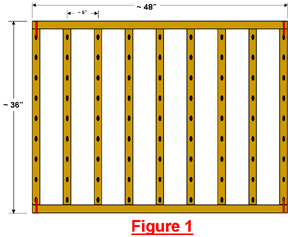
Wood glue nine of the 33Ľ” and two of the 47˝” redwood pieces together as shown in Figure 1. When clamping the glue
joints, assure that the frame is as square as possible (measure and match opposite corners).
Do not install the screws shown in red in Figure 1 at this point.
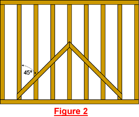
Cut the diagonals (26” redwood) to fit as shown in Figure 2. Glue at all intersections with the verticals
(7 points).
 STEP 3 - Build the back frame
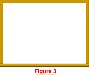
Wood glue two of the 33Ľ” and two of the 47˝” redwood pieces together as shown in Figure 3. When clamping the glue
joints, align to the front frame.
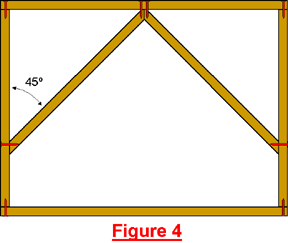 Cut the diagonals (34” redwood) to fit as shown in Figure 4. Glue into place.
Drill guide/relief holes and install eight of the 2Ľ” flathead screws at the locations shown in Figure 4.
 STEP 4 - Prepare dowels for rockets with T-engine retainers (optional)
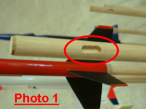
If you have T-engine rockets that have the Estes-style engine retainer clips, you might consider routing out a small
groove in some or all of the dowels so that the retainer clip won’t be bent out while in storage. See Photo 1.
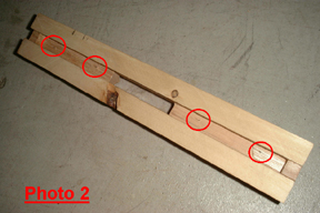 The groove I made was 3/16” wide, ˝” long, and centered about 2” from the end of the dowel. I used a
Dremel/router
bit in a router table in conjunction with a jig for holding the dowel during the routing process. This jig, shown in
Photo 2, has four finishing nails nailed in from the backside such that the points hold the dowel in place.
The groove I made was 3/16” wide, ˝” long, and centered about 2” from the end of the dowel. I used a
Dremel/router
bit in a router table in conjunction with a jig for holding the dowel during the routing process. This jig, shown in
Photo 2, has four finishing nails nailed in from the backside such that the points hold the dowel in place.
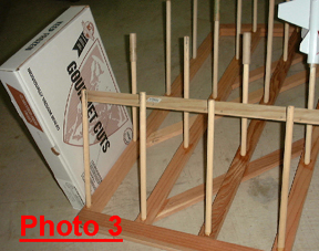 STEP 5 - Install the dowels
Because there will typically be some slop in the bore-holes made in Step 1, and the ˝” dowels will also vary slightly
in actual diameter, use of a dowel-positioning guide as shown in Photo 3 is recommended. The crossbar is located
such that when the dowels lean against it, they will all be at 60 degrees to the front frame. Marks at the
appropriate locations on the crossbar allow the dowels to also be aligned to be mutually parallel.
Working one row at a time, position the guide, glue and align the dowels, let dry. Repeat for next row.
After the dowels are set, drill guide/relief holes and install four of the 2Ľ” flathead screws at the locations in
the front rack as shown in Figure 1.
 STEP 6 - Install the main hinges
Install the four 2” x 1Ľ” hinges long the top of the front and back frames, such that they are centered at
approximately 2” and 16” from each end. There will be a small gap between the frames. See Photo 4.
 STEP 7 - Install limit cords
This is the mechanism that prevents the rack from over-extending when in the “open” position. See Photo 5.
Install four screw-eyes, one at the lower end of each front frame diagonal (on the backside) and one directly
opposite it on the lower bar of the back frame (along the top edge). See Photo 6.
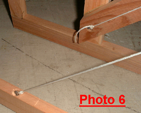 I chose to sink the screw-eyes below the wood surface, as this prevents the front frame screw-eyes from marring the
wall when the rack is in the hanging position.
I chose to sink the screw-eyes below the wood surface, as this prevents the front frame screw-eyes from marring the
wall when the rack is in the hanging position.
With the rack standing in the open position as it would on the field, tie one piece (approximately 5’ long) of the
1/16” braided nylon cord from one screw-eye on the front frame diagonally across to the screw-eye on the back frame.
Repeat with the other cord and screw-eyes, forming the “X” shown in Photo 5. Adjust the cord length as necessary.
 Install the last screw-eye at the bottom side of the juncture of the back frame diagonals. Attach the bungee cord
(I used a 1/8” sleeve and swaging tool) to the screw-eye. Now, with the rack in the closed position, attach the
other end of the bungee cord around the center of the “X” formed by the two nylon cords such that the cords are just
barely pulled up to their highest vertical extension. This should position the cords immediately behind the front
frame diagonals and therefore “out-of-sight”. See Photo 7.
Install the last screw-eye at the bottom side of the juncture of the back frame diagonals. Attach the bungee cord
(I used a 1/8” sleeve and swaging tool) to the screw-eye. Now, with the rack in the closed position, attach the
other end of the bungee cord around the center of the “X” formed by the two nylon cords such that the cords are just
barely pulled up to their highest vertical extension. This should position the cords immediately behind the front
frame diagonals and therefore “out-of-sight”. See Photo 7.
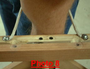
STEP 8 - Install carrying straps
Cut a portion of the Ľ” braided nylon cord (approximately 10” to 12”), melt the ends, and attach to the top edge of
the back frame with two ľ” screws and washers, with a spacing between the attachment points of approximately 6
inches. See Photo 8. This functions as a stabilizer when carrying the rack by the lower handle, so your arm must be
able to fit through it up to your elbow.
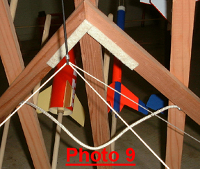
 Cut another portion of the Ľ” braided nylon cord (approximately 16”), melt the ends, and attach to the bottom edges
of the front diagonals, approximately 8” from their juncture. When carrying the rack by this lower handle, your hand
may rub against the edges of the front rack diagonals. To protect your hand, attach felt pads along those edges as
shown in Photo 9.
Cut another portion of the Ľ” braided nylon cord (approximately 16”), melt the ends, and attach to the bottom edges
of the front diagonals, approximately 8” from their juncture. When carrying the rack by this lower handle, your hand
may rub against the edges of the front rack diagonals. To protect your hand, attach felt pads along those edges as
shown in Photo 9.
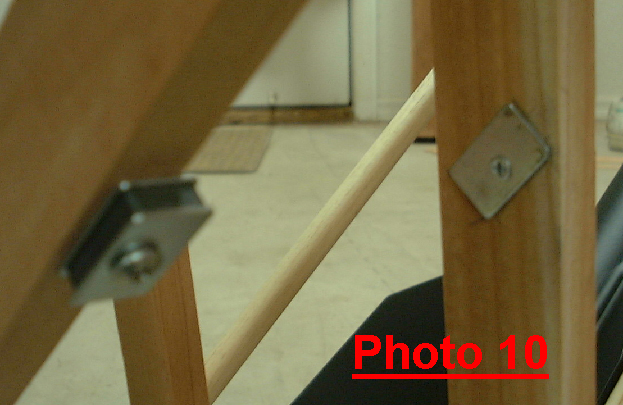
STEP 9 - Install magnetic latches
These latches keep the back frame snug up to the front when the rack is being carried. Attach the magnet portion of
one of the latches to the underside of one of the back frame diagonals, at the point that the diagonal intersects the
second-from-the-end vertical. See Photo 10. I removed the magnet (and side plates) from its plastic housing for
esthetic reasons.
 Attach the plate portion of the latch to the vertical.
Repeat on the other diagonal.
 STEP 10 - Install eye bolts
The eye bolts are used to hang the rack on a wall, so you probably want to first determine where it will be hung and
install the Ľ” lag screws (or alternative attachment method). Then install the eye bolts at the appropriate
positions in the top bar of the back frame. See Photo 11.
STEP 11 - Adapters
To store rockets using other than T engines, you’ll need “adapters”. These are just cleaned-out spent engine
casings, flipped over so the nozzle end goes into the rocket’s MMT. For D- or E-engine rockets you’ll need two
casings: a A/B/C glued into the inside of the D or E (remove the nozzle from the D/E). Beveling the casing’s
internal and external edges will make it easier to fit both onto the dowel and into the rocket’s MMT.
TRANSPORT LEGS (OPTIONAL)
I added these after discovering that the rack was just a tad too large to fit in my Explorer, but that when angled -
so that the rockets pointed straight up - it was just fine. Here is a photo of how they work:

 STEP 12 - Prepare the leg verticals
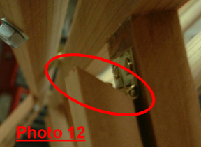
Trim the top edges of the 15ľ” redwood pieces at about a 45-degree angle. See Photo 12.
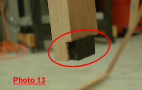
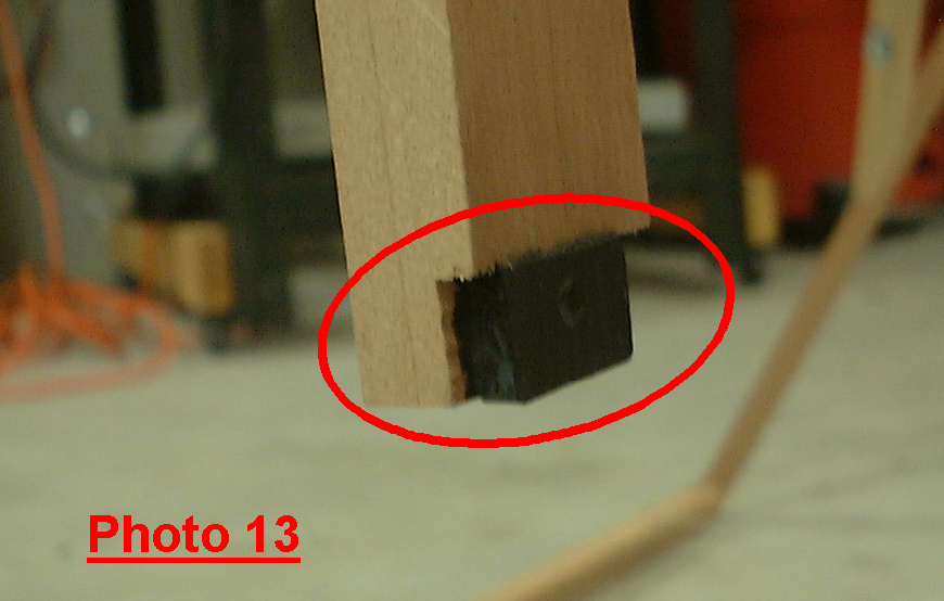
Remove the magnets from the two magnetic catches. Cut out an area of the side of the leg vertical at the bottom -
approximately 1/8” deep, ˝” high, across the width of the leg (or otherwise to accommodate the magnet). Glue magnet
in place. See Photo 13.
 STEP 13 - Install the leg verticals
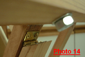
Attach a 1” x 1” hinge to the angled end of the transport leg vertical. Then attach the hinge to the front frame
vertical (2nd from the end) as high as possible. Make sure that the leg can swing out without bumping the front
frame’s top crossbar and that it does not interfere with the back frame diagonal when the back frame is closed. See
Photo 14 for the hinge positioning.
Repeat for other leg.
STEP 14 - Prepare and install the leg diagonals
Cut the diagonals to fit as shown in Figure 5. Also trim the top edges at about 45 degrees as in Step 11.
Attach a 1” x 1” hinge to the angled end of the transport leg diagonal. Then attach the hinge to the front frame
vertical (4th from the end) as high as possible.
Drill a guide hole and install a 2Ľ” flathead screw at the location shown in Figure 5 (also glue the joint).
Repeat for other diagonal.
 STEP 15 - Install magnet plates
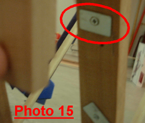
Attach the magnet plates to the front frame vertical just behind the magnets. See Photo 15.
Back to BARCLONE


 STEP 1 - Drill the dowel holes
 STEP 2 - Build the front frame
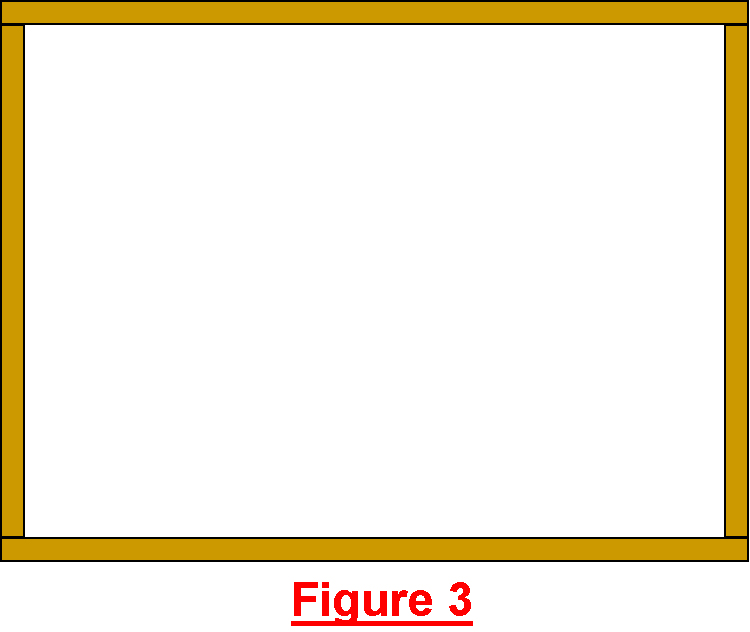 STEP 3 - Build the back frame
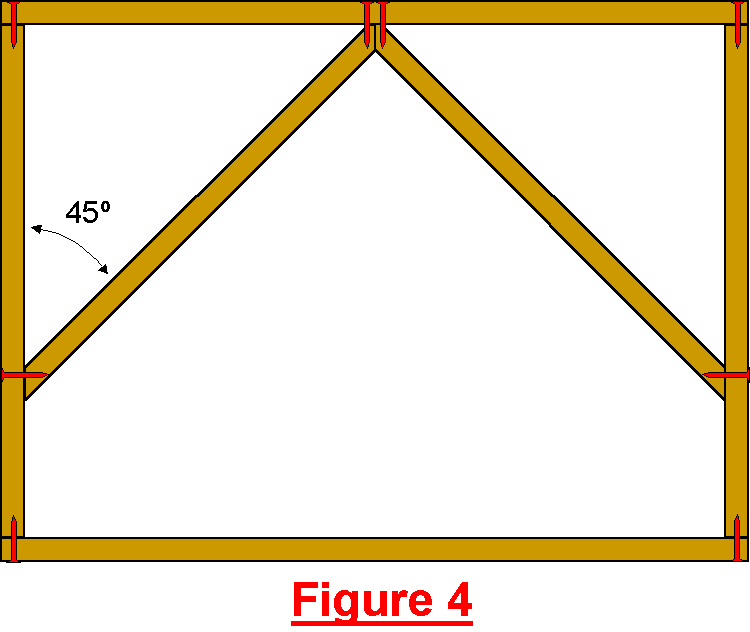 Cut the diagonals (34” redwood) to fit as shown in Figure 4. Glue into place.
 STEP 4 - Prepare dowels for rockets with T-engine retainers (optional)
 The groove I made was 3/16” wide, ˝” long, and centered about 2” from the end of the dowel. I used a
Dremel/router
bit in a router table in conjunction with a jig for holding the dowel during the routing process. This jig, shown in
Photo 2, has four finishing nails nailed in from the backside such that the points hold the dowel in place.
The groove I made was 3/16” wide, ˝” long, and centered about 2” from the end of the dowel. I used a
Dremel/router
bit in a router table in conjunction with a jig for holding the dowel during the routing process. This jig, shown in
Photo 2, has four finishing nails nailed in from the backside such that the points hold the dowel in place. STEP 5 - Install the dowels
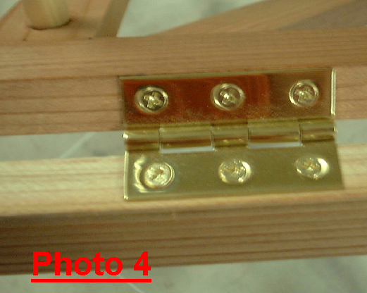 STEP 6 - Install the main hinges
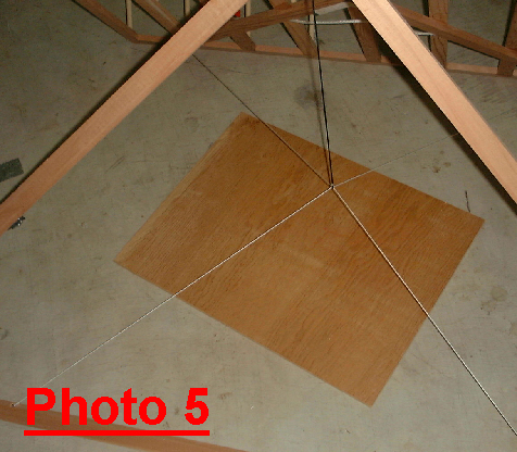 STEP 7 - Install limit cords
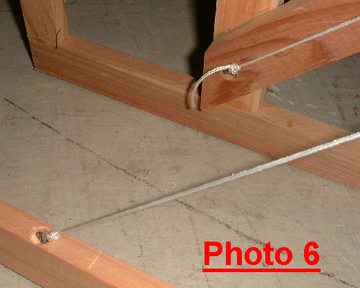 I chose to sink the screw-eyes below the wood surface, as this prevents the front frame screw-eyes from marring the
wall when the rack is in the hanging position.
I chose to sink the screw-eyes below the wood surface, as this prevents the front frame screw-eyes from marring the
wall when the rack is in the hanging position.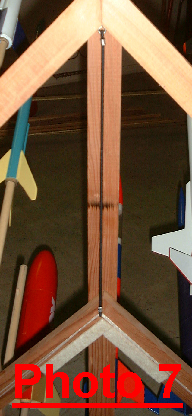 Install the last screw-eye at the bottom side of the juncture of the back frame diagonals. Attach the bungee cord
(I used a 1/8” sleeve and swaging tool) to the screw-eye. Now, with the rack in the closed position, attach the
other end of the bungee cord around the center of the “X” formed by the two nylon cords such that the cords are just
barely pulled up to their highest vertical extension. This should position the cords immediately behind the front
frame diagonals and therefore “out-of-sight”. See Photo 7.
Install the last screw-eye at the bottom side of the juncture of the back frame diagonals. Attach the bungee cord
(I used a 1/8” sleeve and swaging tool) to the screw-eye. Now, with the rack in the closed position, attach the
other end of the bungee cord around the center of the “X” formed by the two nylon cords such that the cords are just
barely pulled up to their highest vertical extension. This should position the cords immediately behind the front
frame diagonals and therefore “out-of-sight”. See Photo 7. Cut another portion of the Ľ” braided nylon cord (approximately 16”), melt the ends, and attach to the bottom edges
of the front diagonals, approximately 8” from their juncture. When carrying the rack by this lower handle, your hand
may rub against the edges of the front rack diagonals. To protect your hand, attach felt pads along those edges as
shown in Photo 9.
Cut another portion of the Ľ” braided nylon cord (approximately 16”), melt the ends, and attach to the bottom edges
of the front diagonals, approximately 8” from their juncture. When carrying the rack by this lower handle, your hand
may rub against the edges of the front rack diagonals. To protect your hand, attach felt pads along those edges as
shown in Photo 9.
 Attach the plate portion of the latch to the vertical.
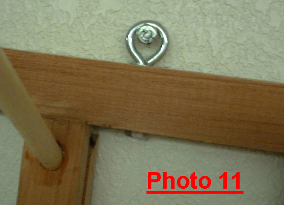 STEP 10 - Install eye bolts
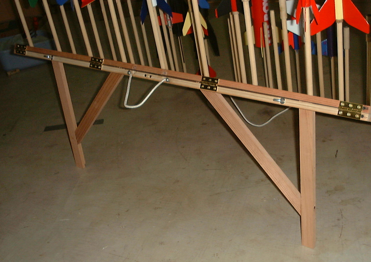

 STEP 12 - Prepare the leg verticals
 STEP 13 - Install the leg verticals
 STEP 15 - Install magnet plates